
PWM (Pulse Width Modulation) is a discrete, time-based signal that can only have two states (0 or 1) within a given period. The amount of time the signal stays at the high (1) level within one period defines the duty cycle.
In contrast, a 0–10 V analog signal can vary continuously at any value within its range and may change multiple times within a single period.
Sometimes, there's a need to convert an analog signal into PWM. I used to find this confusing — how can a continuously changing analog level fit into the fixed-period nature of a PWM signal? Here's how it works.
Analog → PWM Conversion
The key idea in analog-to-PWM conversion is to compare the analog signal with a reference waveform that changes in a known, predictable way. The classic method is to use a triangle wave or sawtooth wave as the reference:
- A sawtooth or triangle waveform with a fixed frequency continuously rises and falls over each period.
- The 0–10 V analog signal is compared to this reference using a comparator.
- Whenever the analog signal is higher than the current value of the triangle wave, the PWM output is 1; otherwise, it's 0.
Even though the analog signal may change within a single period, the PWM signal only reflects it in an average sense over time. If the PWM frequency is high enough, a low-pass filter at the output can effectively reconstruct the original analog signal.
This principle is why PWM is widely used for motor control and LED dimming — at sufficiently high frequencies, the human eye or the electrical system perceives the rapid on-off pulses as a smooth analog output.
Diagram
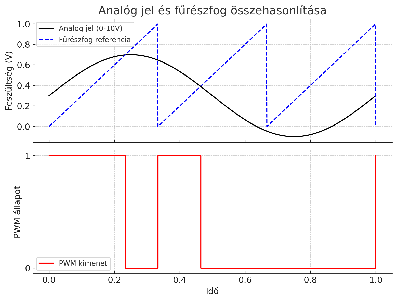
Top diagram (Analog signal vs. sawtooth reference)
- The black line represents the analog input voltage (e.g. varying between 0–10 V).
- The blue line is a repeating sawtooth wave with fixed period.
- The red dots indicate moments when the analog signal is greater than the reference → PWM is HIGH (1) at these points.
Bottom diagram (PWM output)
- When the analog value is higher than the sawtooth at a given moment, the PWM output is 1 (HIGH).
- When it’s lower, the output is 0 (LOW).
- The duty cycle of the PWM is proportional to the analog input value.